|
|
Tutorial | |
MIDI control electronic boards available here can be used to MIDIfy almost anything. They are building blocks, each having different role in the system, but they all work together, combined in a single controller with one "MIDI OUT" socket, sometimes also "MIDI IN". It's up to you what to do with those electronic modules, there are many configurations available. Here are presented only a few typical ones.
But first we start with short overview of basic setup procedures, that apply to all master controllers in every configuration. They can be done either from special Keypad, or any keyboard scanner, but to make it nicer and more user friendly, let's assume there is also the MiDisp in the system.
Setup procedures overview
|
The most important is to tell the MIDI controller what keyboard, or pot you want to edit. Do it by playing a note on this keyboard, or if it is potentiometer - turn it a bit. Every setup procedure described here (and those more advanced too) is done to this specific input selected prior entering EDIT mode. To enter EDIT mode press # on the keypad, or use EDIT pin in the master board. This precedence defines which input will be further edited. |
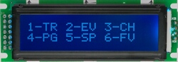
Ater you press # button, or short EDIT pins, this shows up, 1-TRansposition, 2-EVent setup, 3-CHannel setup, 4-ProGram change, 5-SPlit point, 6-FaVourite programs.
To escape from this menu, press 0.
|  |
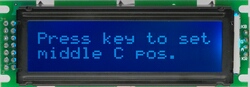
| if you then select 1 (transposition), another screen appears, asking to press the key on the keyboard, where you want to hear the MIDI note middle "C".
|  |
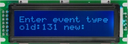
| To change event assigned to any input, from the main menu select 2-EV, and you will see this screen, showing what is the actual event assigned to the last played control, with a space for new number
|  |
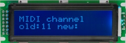
| Likewise, to change channel, select 3-CH from the main menu, and you will see the following screen. Again there is previous value assigned for last used input, and have a chance to enter new channel number
|  |
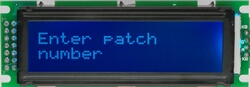
| To generate Program Change message, or in human language - to change the voice of instrument, press 4 from the main menu and you will see this screen. Then enter 3-digit program number(001-999), and it will be calculated to proper bank and program, according to MIDI specification.
|  |
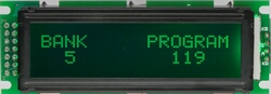
| after 3rd digit master controler sends 3 messages: Bank Select MSB, Bank Select LSB and Program Change. Bank is sent only in MSB, as used in most instruments. LSB is always 0. Actual program number and bank is then displayed in green on this screen
|  |
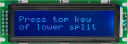
| To split keyboard in 2 independent parts, select 5-SP from the main menu, and the following screen appears. All you need to do then is to press the top key of lower split. After that the setting is done and memorized.
|  |
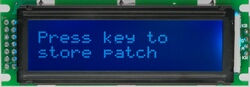
| There are 64 memory locations in master controller, where you can store your favourite Program Numbers in any sequence. You must first select the program number by any available means, for example using #4 command. Always the last sent Program Change number is saved into that memory. So after it was already selected, simply press # to get into main menu, then 6 (FV) and the following screen appears. To define what what's the memory location for selected program number press any of 64 inputs of any keyboard scanner. So if you have a series of buttons designated to this task (assigned to event 134) - press one of them and the number is stored. Refer to master controller manual for details.
|  |
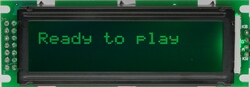
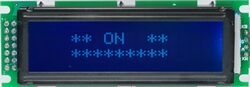
| After each setup procedure the display indicates that master controller returned to normal operation by changing backlight to green. Most of the times it displays this screen, but for example after selecting program (#4) you will see the numbers
| 
|
|
How to use LCD modules with Hauptwerk
There are 2 kinds of 2x16 LCD modules available. Standard size with multicolor backlight - MiDisp, and smaller one with white letters on black only - miniLCD. Each of them (MiDisp since version 2.0) can be used to display text messages from Hauptwerk if connected to MRG2 (v2.4 required). Also, the backlight of MiDisp changes according to color settings in Hauptwerk.
You need MRG2 in version 2.4 or higher to see anything on the LCD, but apart from displaying messages, the same MRG2 can be used to MIDIfy all keyboards, pedals, and other controls of the organ. There are only few things to prepare with MIDI boards in order to recognize and display text.
First of all connect all LCDs in the system as one chain. If there is more than 10 units, you must use power extender. This can be ordered separately, or you can do it yourself. It's only a matter of supplying 5V to more units than internal regulator of the master controller can provide. Pictures below show how to connect LCDs in series. One connector of LCD always goes towards MRG2, the other one - to another LCD, or other scanner. If you reverse the cables - it will not work.
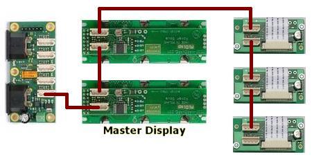
First LCD connected to MRG2 becomes Master Display, that shows all user config messages from MRG2. Whenever a new text comes in from Hauptwerk, it will overwrite whataver the display showed before.
At the back of LCD module there are 2 pads to connect a switch. It can be used as additional input in MIDI system, for example can control organ rank. This switch is also important during preparation for Hauptwerk messaging. In Hauptwerk, all messages are sent to LCD modules with specific number, and this is how you can set this number to each LCD. It is assumed that you also have the KEYPAD connected.
|
press the button connected to pads at the back of LCD, or use a wire to short them for a moment. The following screen appears on this module
|  |
| Use KEYPAD to enter #914 sequence, and last selected LCD will show this message
|  |
Next, enter the number you want to associate with Hauptwerk LCD ID. Always enter 2 digits, so available range is 00 to 99 (LCD001 - ID000 to LCD100 - ID099 in Hauptwerk). After 2nd digit the LCD confirms its newly assigned ID.
| 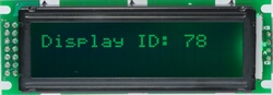 |
At any time you can check the IDs of all LCD in the system. To do so, press a switch of any of the LCDs, and enter #920 from KEYPAD. All LCDs will then show their IDs. When all numbers are set, there's one crucially important setting to be done in MRG2 alone - you must disable MIDI merging function in MRG2, to avoid MIDI loops, that may halt your computer. Play any note on any keyboard, or the numeric KEYPAD, then enter #972, and master display will show message "merger disabled". Now you can safely connect MIDI out of your computer to MIDI IN of MRG2.
It's time for Hauptwerk setup - please refer Hauptwerk manual for Advanced MIDI settings -> LCD
Here's short video showing setup required on MIDI side, assuming Hauptwerk config is already done, and Hauptwerk's status display ID is "4":
|
MIDI controller for virtual synth
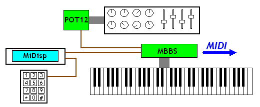 This is an example of small, but versatile MIDI controller. It consists of one keyboard, a few knobs, faders, and a display with keypad. The keyboard contacts are connected to MBBS: 5-octave MIDI encoder. It uses contacts with common ground, so one wire goes to every contact. To add knobs and faders you can use one or more scanners for potentiometers. In this example there's only one, but you can build a chain of those up to 64 potentiometer inputs. There is also a alphanumeric display with 2 lines of 16 characters, and numeric keypad to alter all settings, and send Program Change by the numbers.
SETTINGS:
This setup works stright of the box. Of course you may want to change MIDI CC numbers and chanels assigned to potentiometer inputs. Refer to MBBS user manual for more details.
|
3 keyboards and pedals
This is how to convert old organ to MIDI in a few steps, including 3 keyboards and pedals. No additional controls, but that's already powerful instrument. Each keyboard uses BBS-1K keyboard scanner, while pedals are connected with small 32 input scanner - BBSP. Both kinds of scanners are designed for keyboards with common ground for all contacts in a keyboard/pedal. Most of keyboards present in odler organ consoles are built like this, so it is very easy to MIDIfy this way. Simply connect one wire for each contact.
It is most important to connect ground to keyboard's common rail properly. It may be a separate wire going to the point where the (-) lead of master controller's screw terminal is connected (preffered solution). Optionally the common rail may be connected to the ground of associated keyboard scanner, for example at the mounting screw hole. But do not use both of these methods at once.
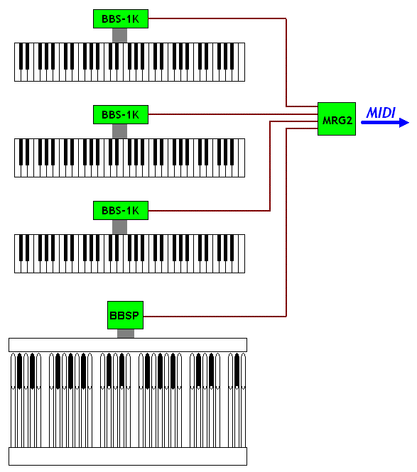
When all contacts are connected, it is time to convert all their activity into one merged MIDI stream. For this purpose in this example we use MRG3 master controller. It has 4 scanner inputs, that means it can merge signals from 4 different scanners (or chains of scanners).
SETTINGS:
This example does not require to change any suer settings from factory defaults. Each of the 4 keyboards/pedals are converted to MIDI in channels 1,2,3,4, and starting note is the same as in most of other instruments (MIDI note 36).
|
3 keyboards, stops, pedals, pistons and swell shoes
Previous example was really only about keyboards, but it is sometimes desirable to add some performance controls, that would be otherwise available at the sound module, or a computer. Here is an example of generously equipped console, with two rows of pistons, long strip of stops, swell/crescendo pedals, and programming keypad with LCD.
Pistons are added with LITSW: LED and button controller split in 2 parts, so it can serve for 2 keyboards. Each piston can be backlit with a LED, so it's indicated what preset was last selected. The expression pedals are connected to analog inputs of BBSP pedal controller, that also takes care of the 32 note pedals. This little board should be installed as close as possible to swell potentiometers, or opto sensors, to avoid interferences. Communiaction between the boards is digital, so the inter-board cable length is not critical here. Typically with BBSP board you get 1.5m cable
Notice that new scanners are added in daisy-chain inputs of BBS-1K. You can always chain up to 2 keyboards like this, together with chain of POT12 scanners for up to 64 pot inputs.
Any equipment without a display does not seem very fancy nowadays. Your MIDI controller is no exception. You can add a display to this setup, and to make it even more friendly to use - small numeric keypad. Both devices are there to help you in user settings. All settings are accessible via the keypad, and every stage of setup procedures is clearly displayed in LCD.
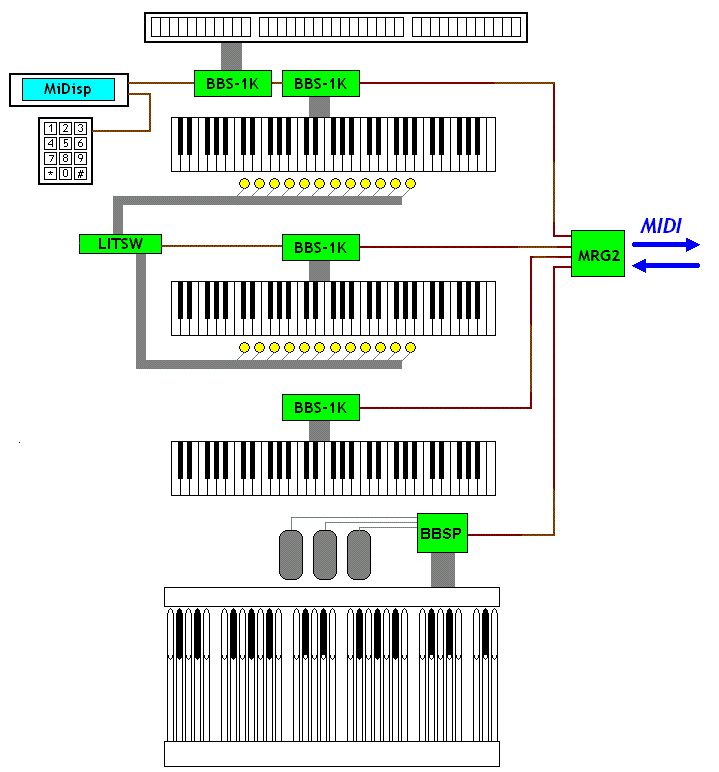
SETTINGS:
To have the LITSW board work for 2 parts, you need to make 2 splits. First the buttons-dependence split, and then functional split, so each part can work in different channel etc. In this example we split LITSW in half and have both parts send Program Change:
- press any piston and enter #905, then press the last button of the 1st group twice - this will set the split of buttons interaction
- enter #5, and again press the last button of 1st group - this will set the functional split, and now both parts can have different MIDI events assigned, and different MIDI channels
- press any button in 1st group, and enter #2129, to make it send Program Change
- do the same for 2nd part - press any button there, and enter #2129
- set MIDI channels in the same way: select the group by pressing any piston of it, and use dial #3 followed by channel number
- press any piston is 1st group, and enter #909 - this will turn it in select-1-of-many mode, so only one piston can be selected at any time
- press any piston in 2nd group, and also enter #909, to make the same dependence mode in this group
- you can also use transposition settings to change starting Program Change number in each part separately.
|
|
|